MVT9 Fatigue Management System
Installation Guide
This installation guide covers the minimum installation and registration requirements for the MVT-9 device utilising the DSM camera only (Driver Facing Camera).
Please follow the link for front facing ADAS camera set up and calibration.
Failing to meet the minimum installation and registration requirements may result in:
The MVT9 system to not operate as intended
LMS to refuse support until requirements are met
If minimum requirements are not met and support is insisted upon, the base support rate will be charged according to the LMS terms and conditions.
Overview
Unboxing and installation preparation
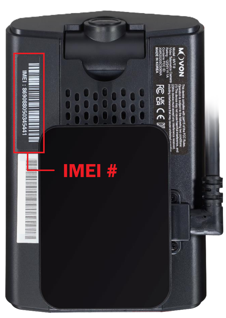
Take photos of the device IMEI number
Mount device and wiring
Position / configure DSM & ADAS cameras
Registration & Commission prior to vehicle release.
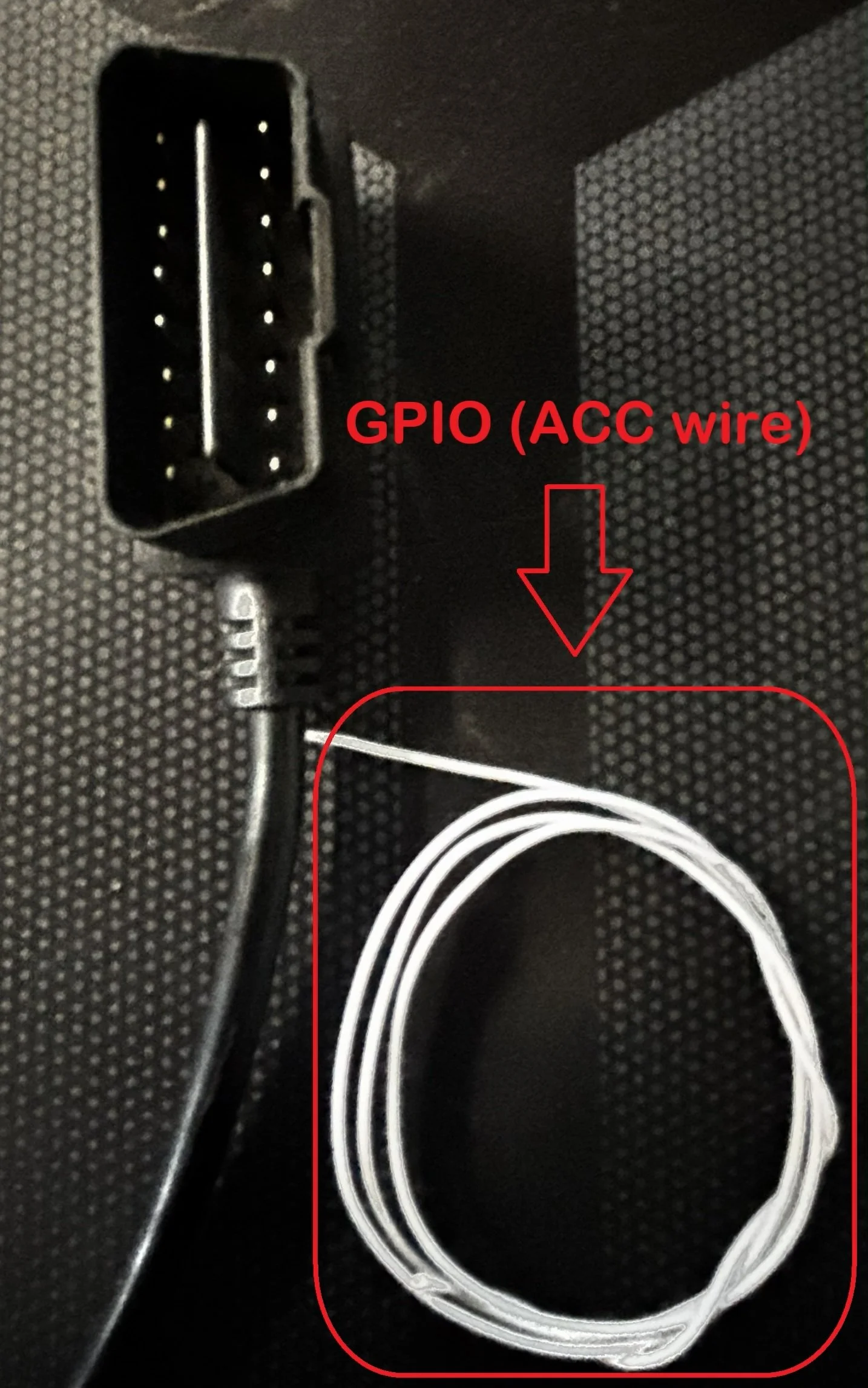
White GPIO wire from the OBDII plug is a separate ACC wire if the OBD port doesn’t have an ignition sense pin
Installation Preparation
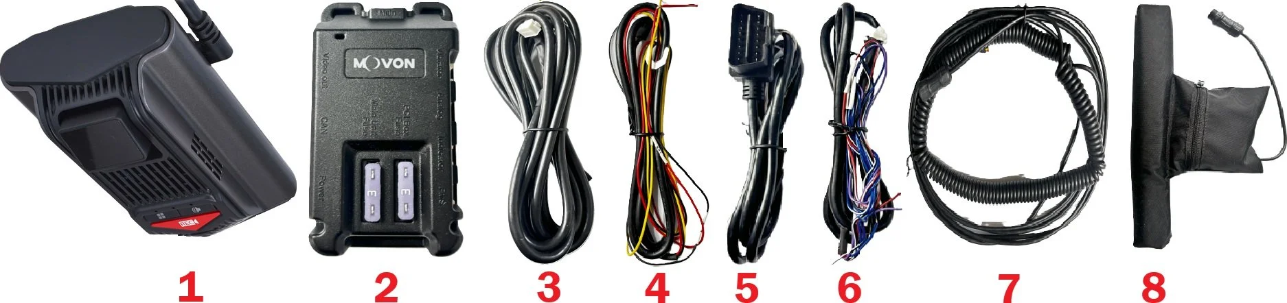
Contents
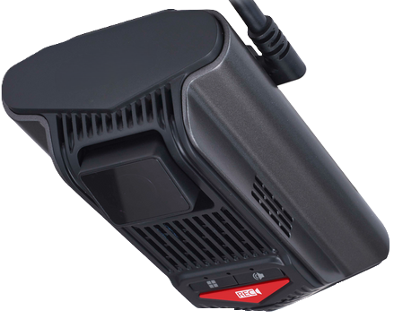
1 - MVT9 Device - w/ SD & Sim Card preinstalled
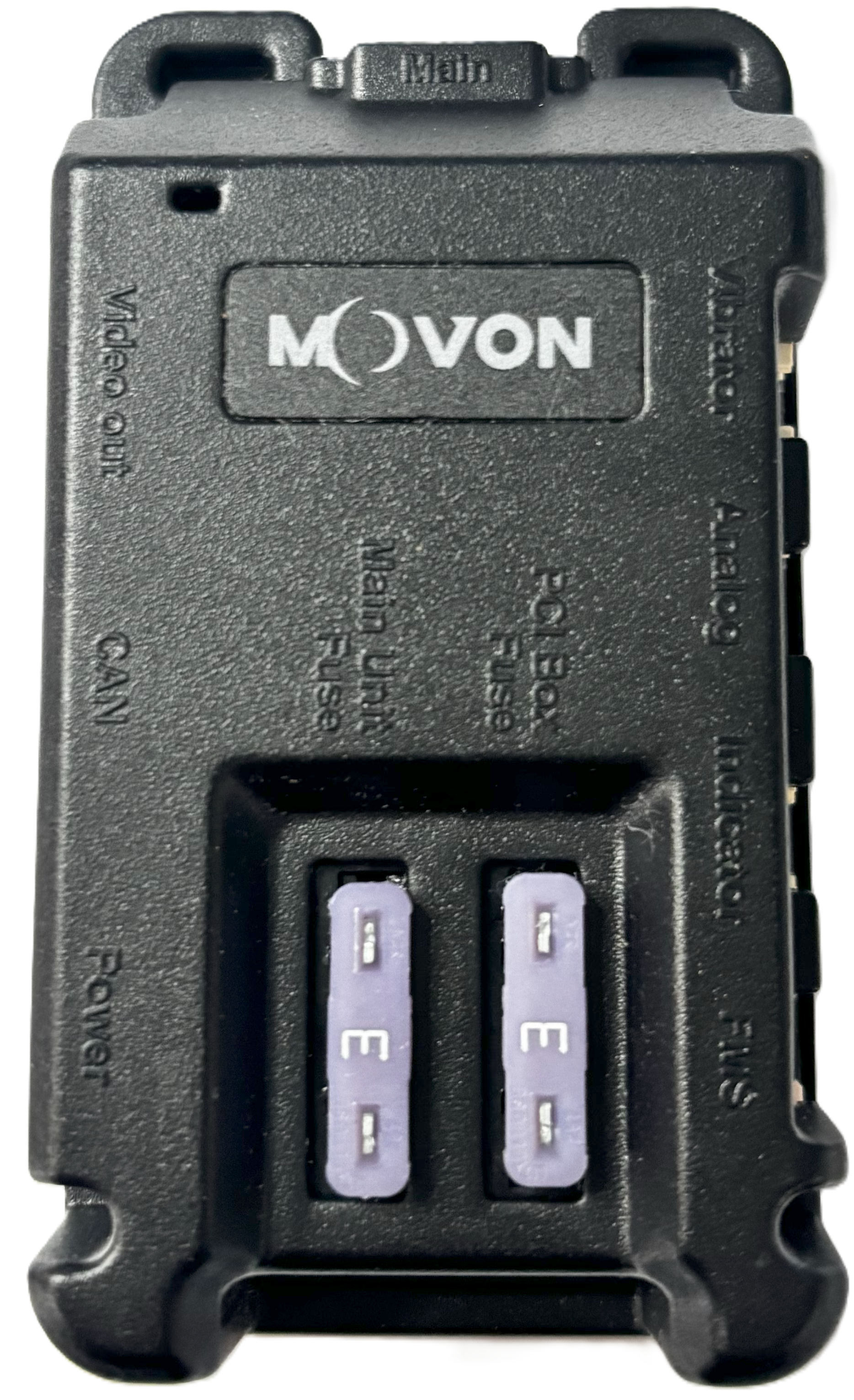
2 - PCI control box - w/ 3a fuse(s)
3 - PCI to MVT9 adaptor harness
4 - 3-wire power cable
5 - OBDII power cable
6 - Input harness
7 - Seat vibration harness
8 - Seat vibration unit
PRO TIP!
We recommend once the device is unboxed, to take a photo of the IMEI number printed on the back side of the device (as shown below) for the registration process at the end.
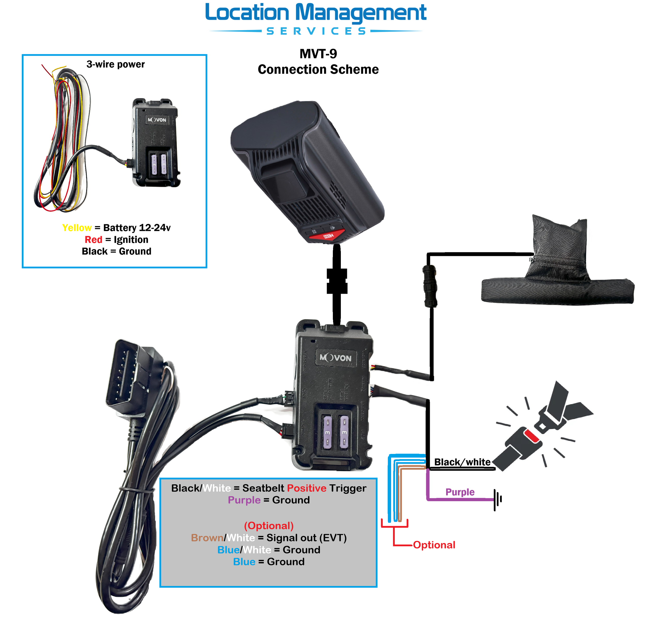
Power supply source
The MVT9 can be powered either by the 3-wire harness or the OBDII cable.
Its recommended to use the OBDII option when available, as the 3-wire option removes CANBUS support.
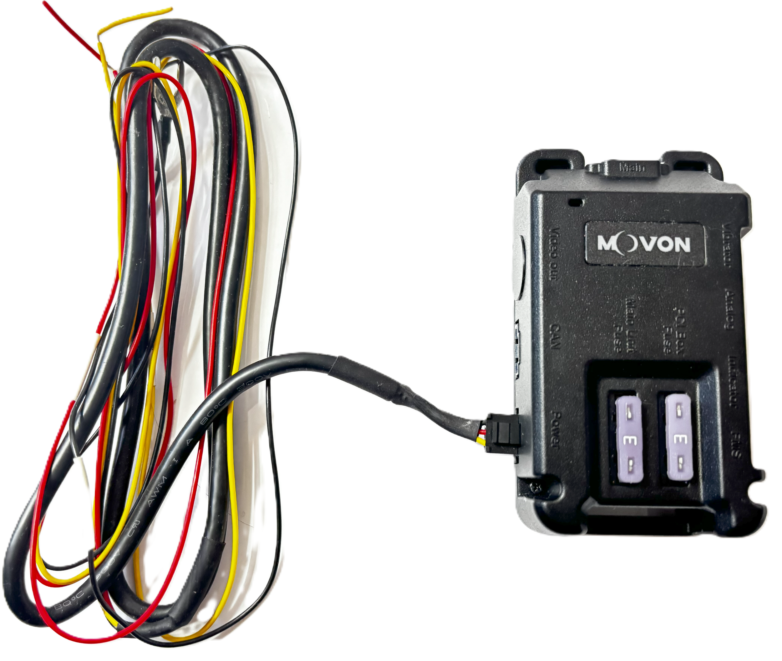
3-wire
Yellow - Battery constant 12-24v
Red - Ignition 12-24V
Black - Ground/Earth
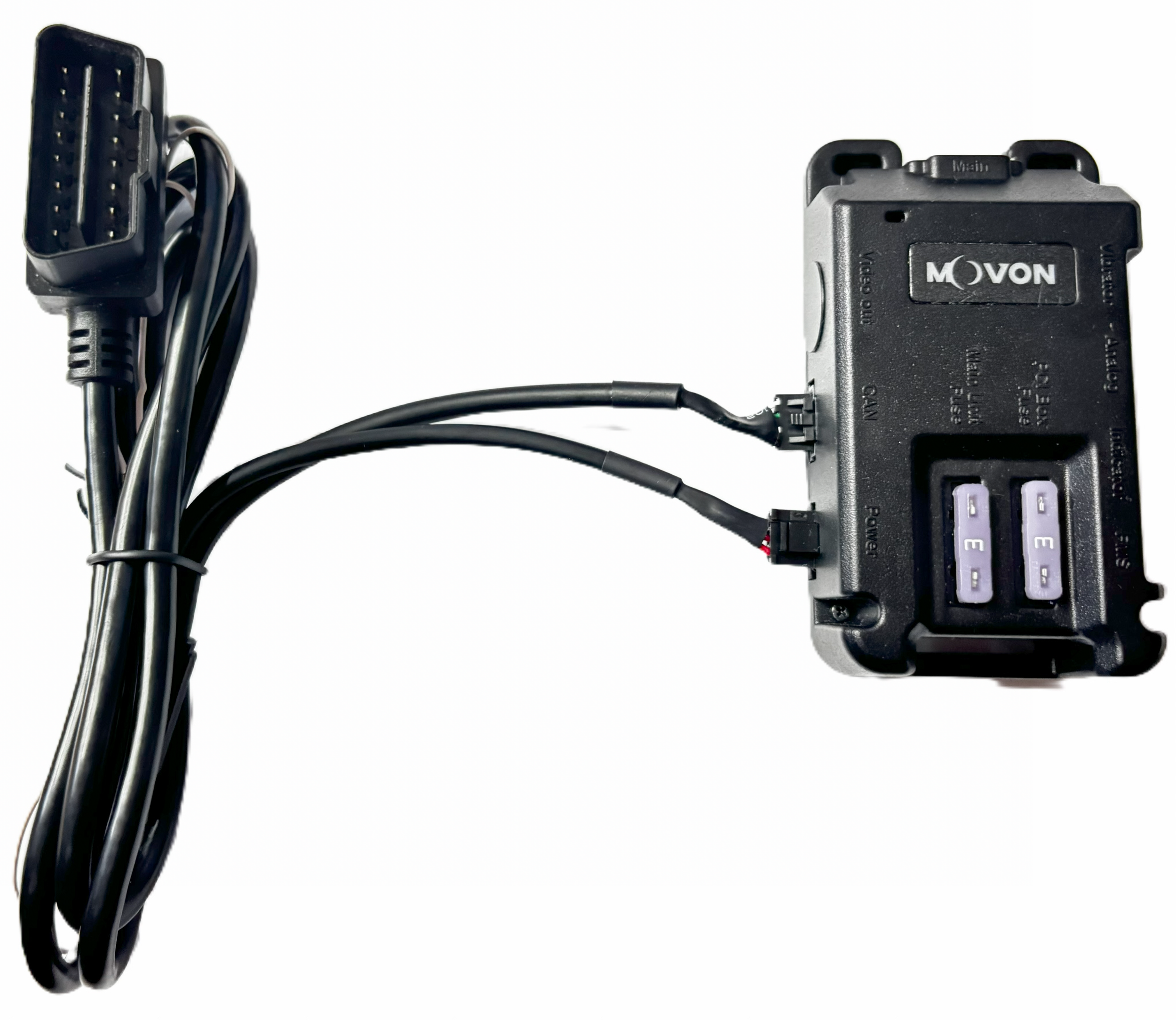
OBDII
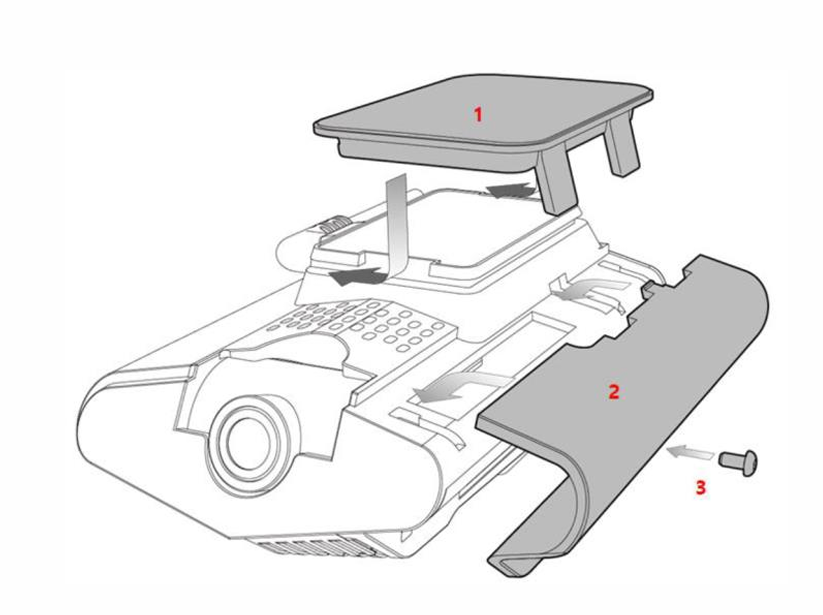
Removing MVT9 from base plate
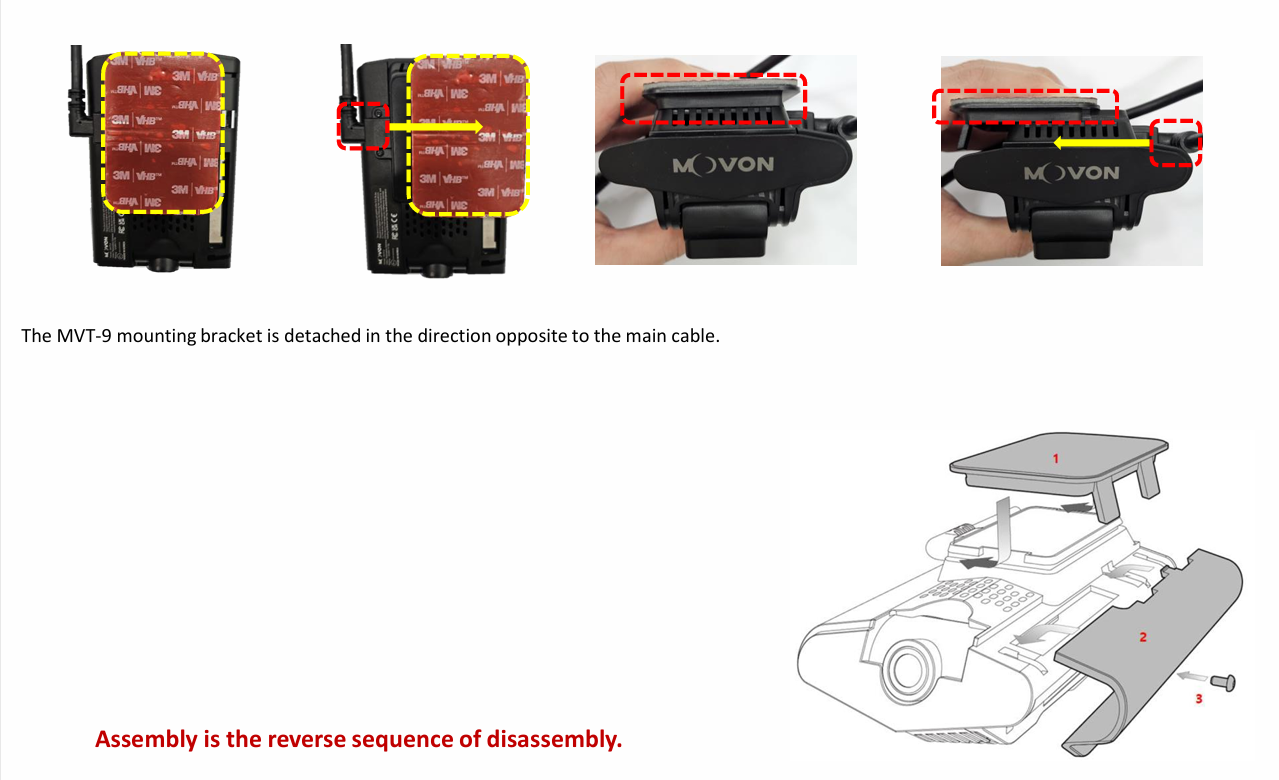
MVT9 Mounting
The ideal mounting position for both the ADAS and DSM camera is just below the rear view mirror in the centre of the windscreen. This will allow the ADAS camera a clear symmetrical view of the road ahead and bonnet of the vehicle.
If this position is obstructing the drivers view, the camera can be moved off centre towards the driver if needed but its not recommended to move more than 30cm from the centre line.
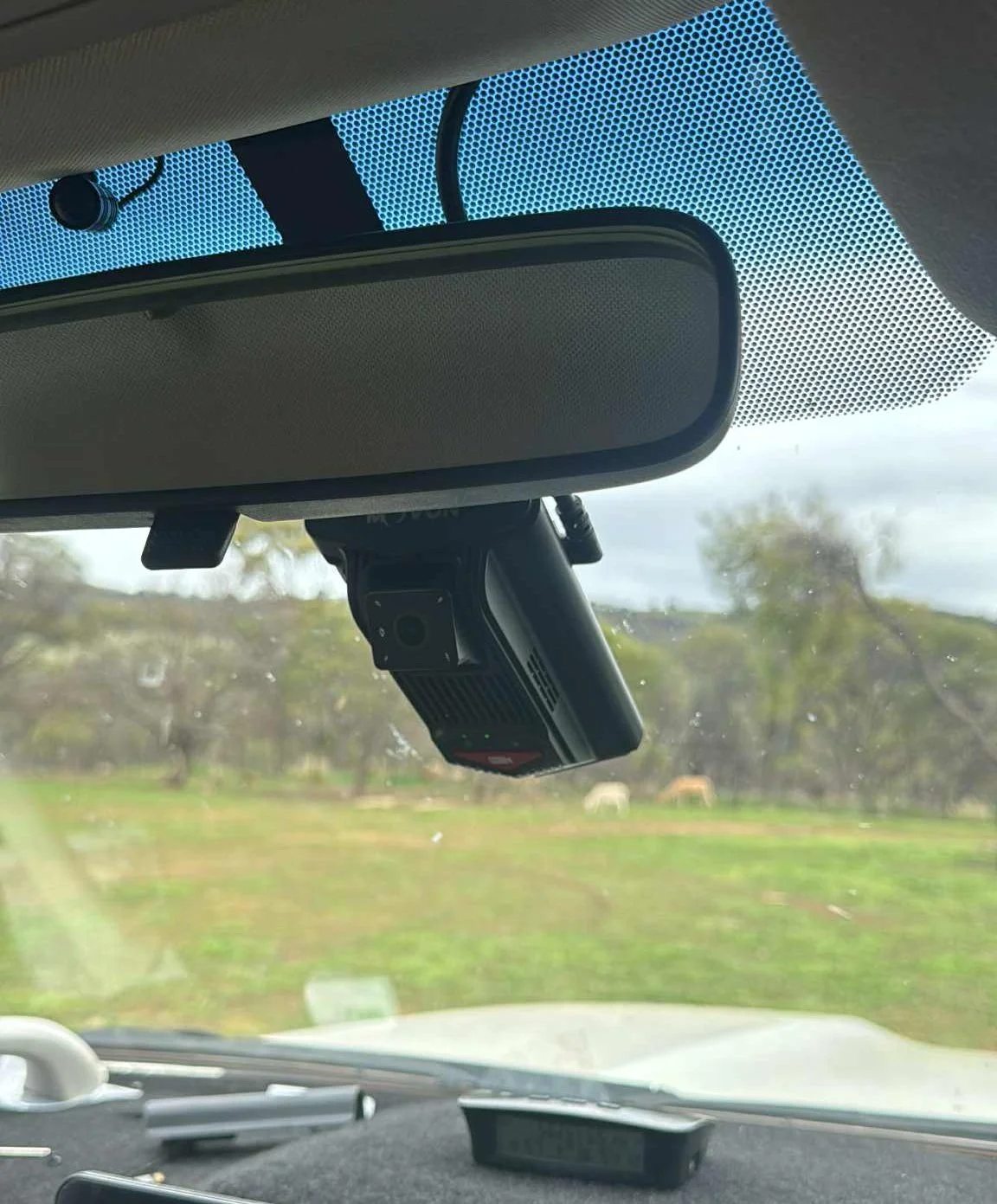
If the MVT9 if being installed in a cab over truck or a vehicle that has a short bonnet, the MVT9 can be mounted lower on the windscreen without blocking the view for the ADAS camera.
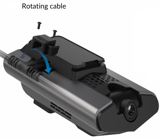
Note: The input cable can be rotated for bottom cable routing
PRO TIP
Make sure the driver facing camera will not be obstructed from sun visors, mirrors or other objects.
Make sure the check full range of movement of possible obstructions before fully mounting the MVT9.
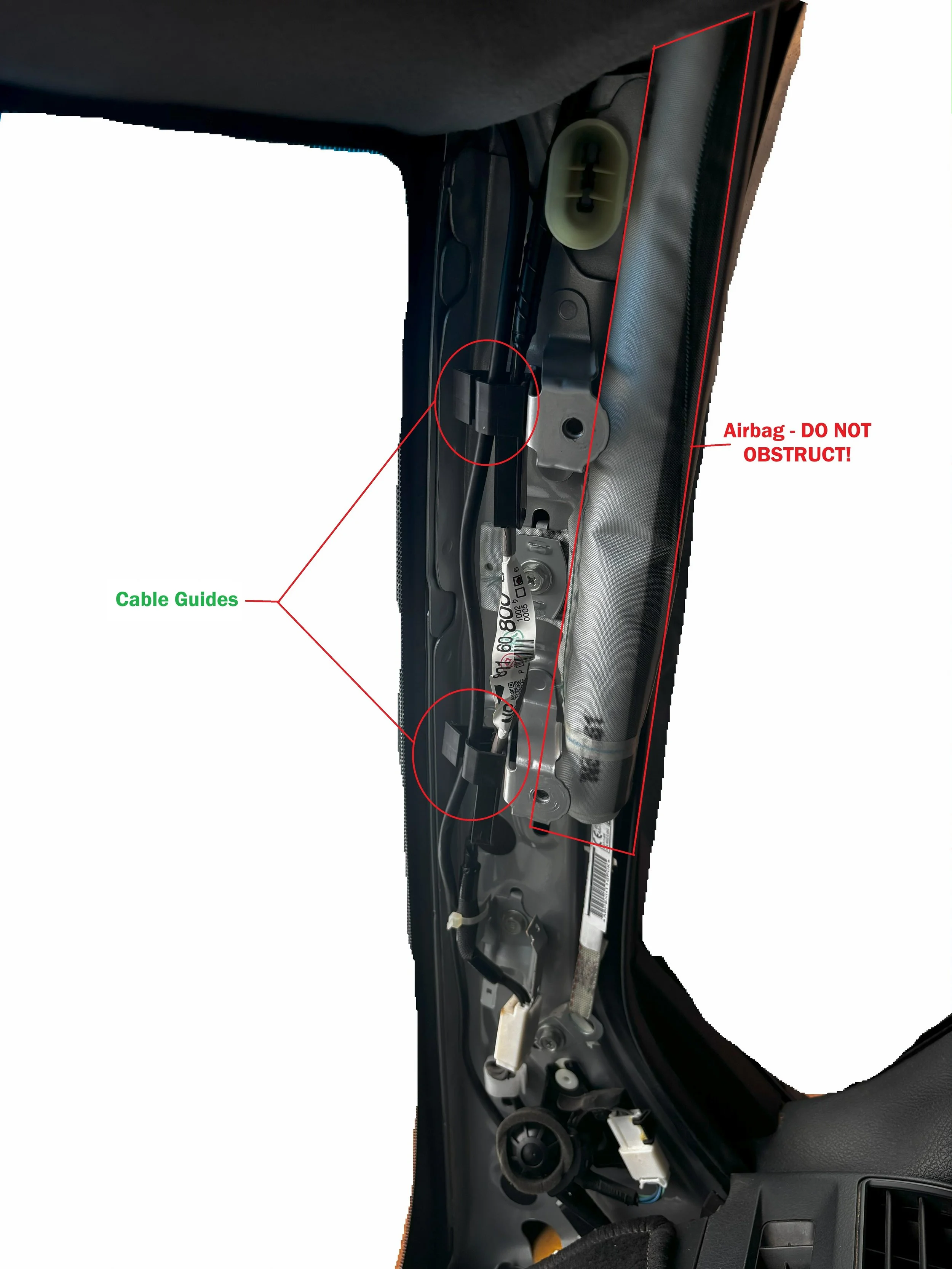
Cable Routing
Make sure all wiring is run neatly, pinned up and does not obstruct any existing component.
Avoid any pinch point, sharp kinks or strain on any of the cables that may cause issues in the future
Pay extra attention when routing cables down the A-pillars, always use factory cables guides or use adequate cable management such as zip-ties.
Make sure no cable / wires obstruct the airbags if fitted.
Seat Vibration Unit
Seat Vibrator Installation & Seatbelt Latch Connection
Materials & wiring spec
Seatbelt trigger lead: 0.5–0.75 mm² (≈20–18 AWG) automotive cable.
Protection: split-loom conduit, fabric tape.
Routing
Route the vibration power and seatbelt trigger leads together in loom for a neat install.
Leave 50–100 mm service loops at moving points (seat rails, height/tilt) so full seat travel doesn’t strain the wiring.
Secure every 150–200 mm to non-moving structures; avoid sharp edges, heaters, and moving mechanisms.
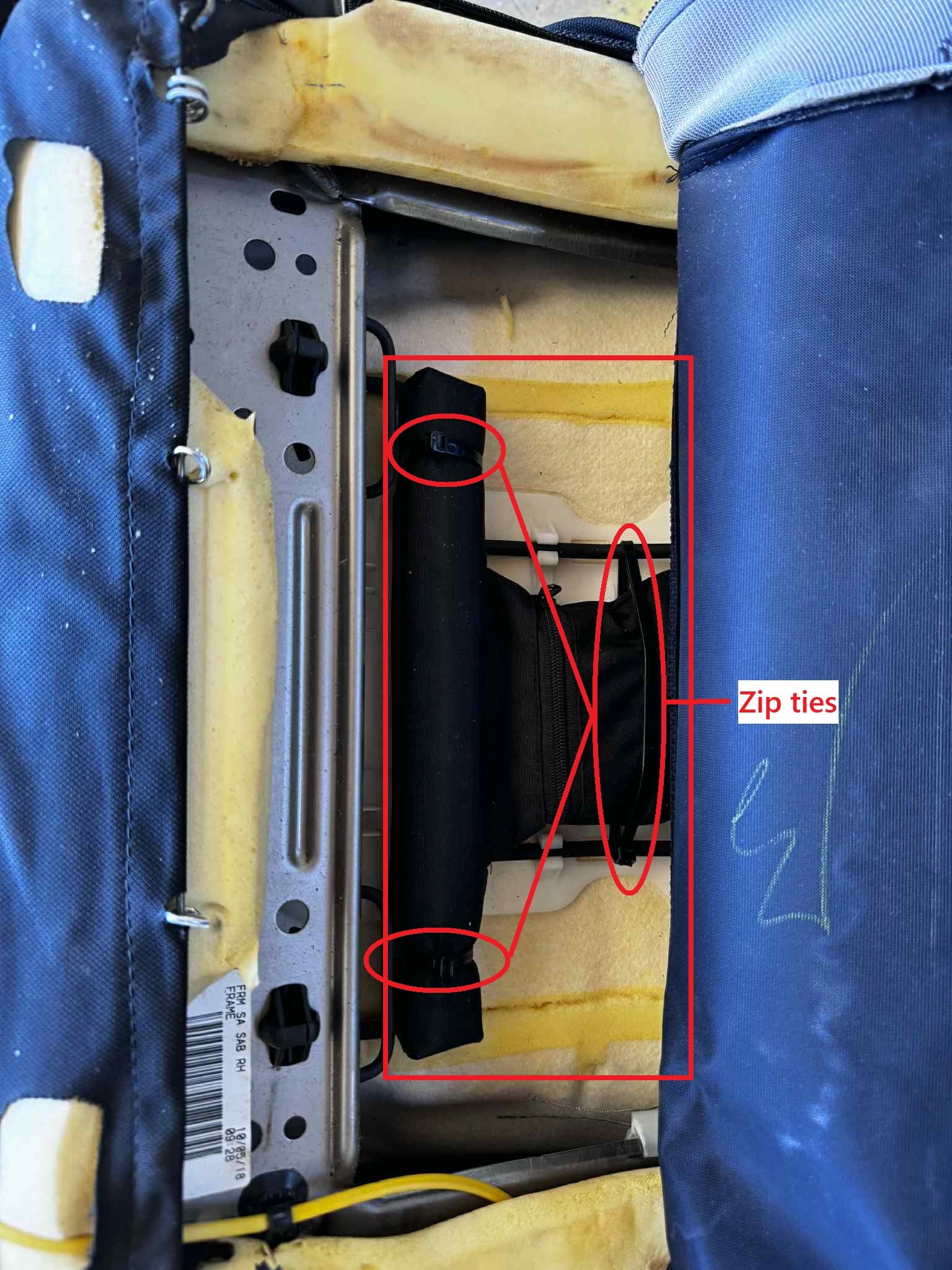
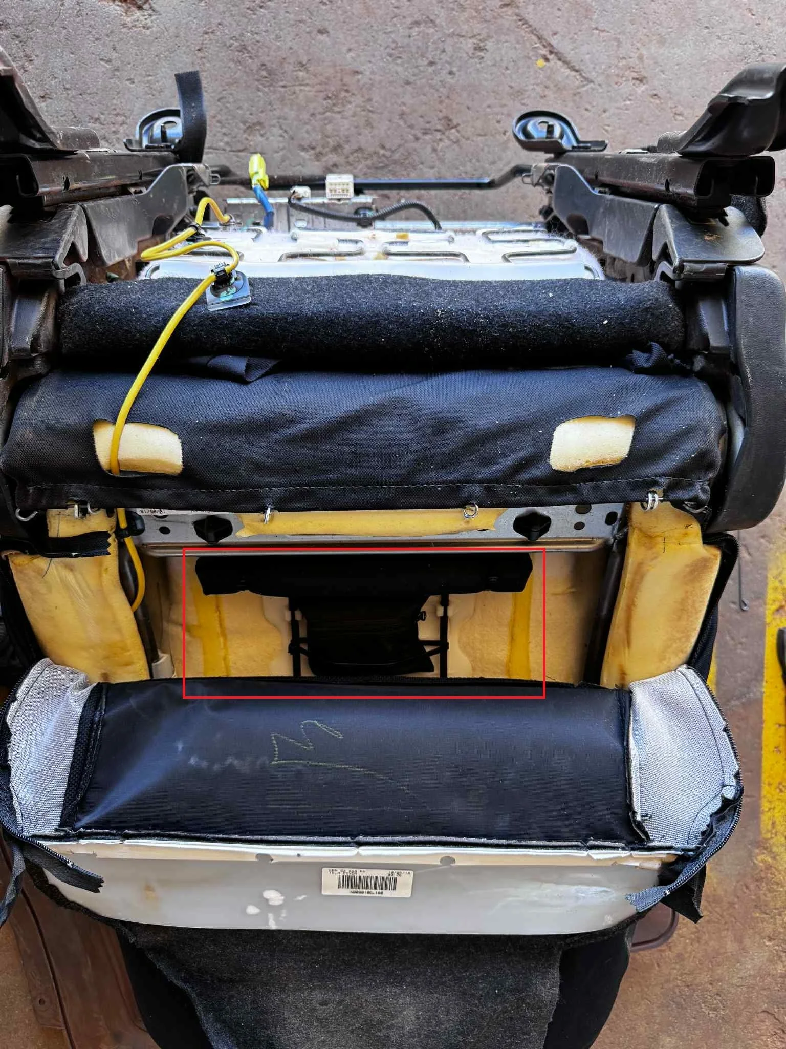
Module mounting
Ensure the module’s power switch is ON (on the vibrator unit).
Mount inside the seat trim where it won’t affect seating position, lumbar, or heaters.
Use zip-ties to secure the vibration module.
After mounting, run the seat through full fore/aft/height travel and confirm no contact, pinch, or change to seating comfort.
Seatbelt latch connection (trigger)
Locate the vehicles seatbelt latch signal wire if available.
Test signal wire by latching and unlatching the seatbelt. Some signal wires are negatively switched.
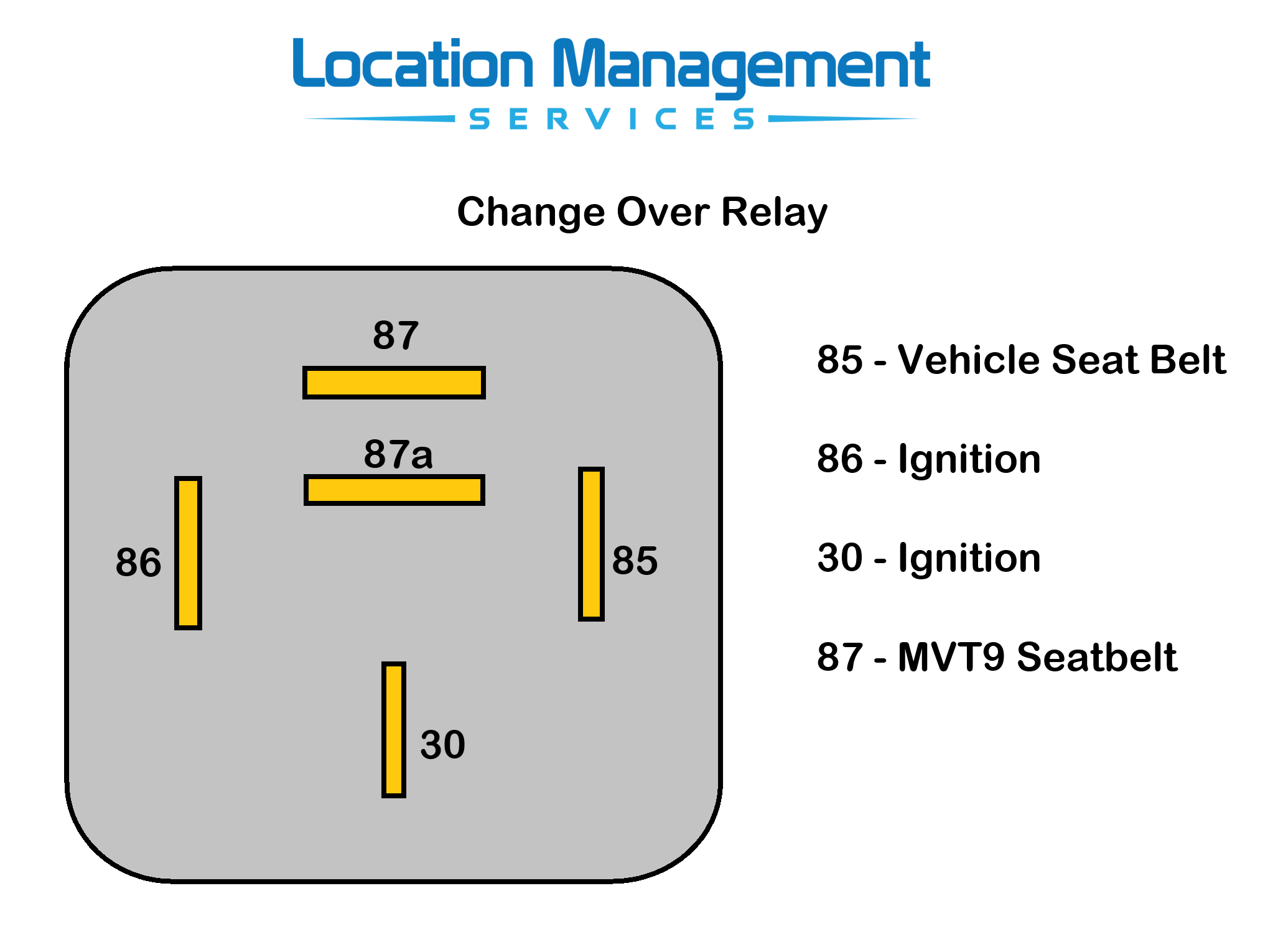
Wiring scheme for seat belt latch:
Black with White stripe connects to the seat belt signal wire
Purple wire needs to attach to ground
For negatively switched vehicles, a relay will need to be wired inline to switch to a positive signal.
Connecting & Mounting PCI Box
All input plugs on the PCI box are unique, simplifying the connection process.
Please note: not all plugs will be populated after installation, as additional accessories may be connected later.
Mount the PCI box underneath the dash using the built-in zip tie eyelets secured to a solid base, or with adhesive mounting tape.
Do not mount the PCI box directly onto a wiring loom. This is not acceptable and may cause interference or connection issues in the future.
Ensure none of the connected wires are under strain or tension. Stress on the plugs may lead to poor connections over time.
Camera Positioning and Commissioning
Once all components have been mounted, connected and powered, its now time for checking the driver facing camera position and tightening the camera locking screws.
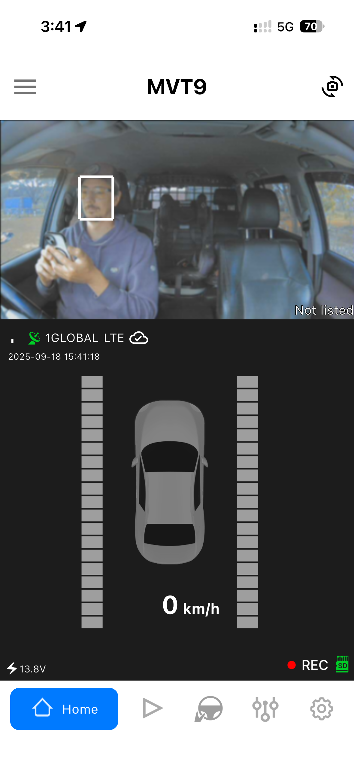
Download the MVT-9 mobile app to check the camera live view.

Open the app and follow the prompts to connect to the device.
Once connected, switch the camera view to show the driver facing DSM camera and make sure the driver is correctly position so the camera picks up the head position
Once the camera is in the correct position, its now time to lock into place using he supplied locking screw
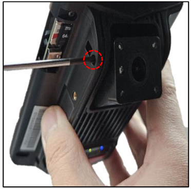
Now refit the anti tamper cover and screw to complete the basic MVT-9 DSM installation