
Fatigue Management System Installation
The minimum installation, updating and commissioning requirements are listed below, failing to meet these minimum requirements can cause limited device functionality and Location Management Services to refuse support.
Basic Installation Overview:
Product Registration
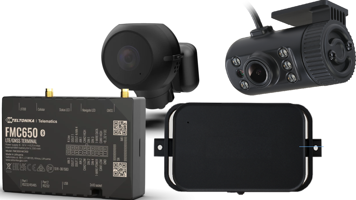
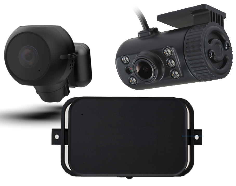
Basic 12/24v wiring and connection scheme for FMC650 and MDSM-22 Camera System
Camera system mobile app update and setup
FMC650 & MDSM-22 (Tracking Device) Testing / Commissioning
MDSM-22 Fatigue Management System installation Guide
Product Registration
It’s recommended to start the product registration prior to installing the fatigue management system.
This allows the installer to layout all components on the bench and take registration photos of the FMS650 (tracking Device) IMEI and object ID’s located on the outer case and complete the product registration via a mobile device for simplicity.
Due to the estimated installation being between 45min to 2 hours, this means the LMS support team can typically have the software side queued for updates and configuration prior to installation completion if not done so already, between business hours.
Wiring Scheme
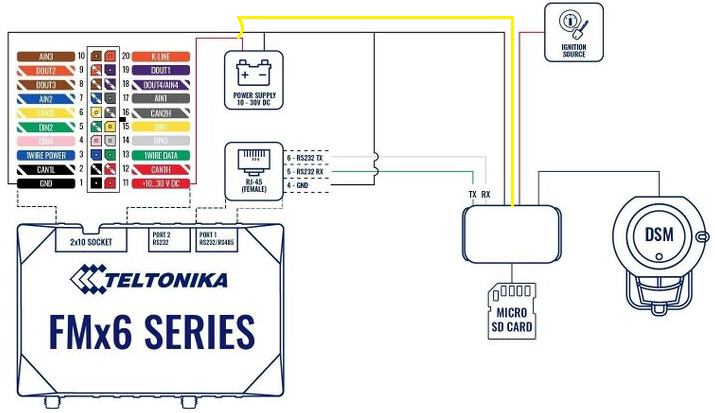
Basic 12/24v wiring guide
FMC650 Tracking Device:
Red Wire = Battery 10-30vdc
Yellow (DIN1) Wire = Ignition 7.5-30vdc
Black Wire = Ground / Earth
White/GRN (DIN2) reserved for Seatbelt latch
Purple (DOUT2) reserved for buzzer negative latch - (Buzzer may be redundant if vehicle is already fitted with factory seatbelt alarm)
LTE / GPS Antennas = Cellular / GNSS SMA male/female plugs
Port 1 RS232 | RJ45 Reserved for MDSM-22 Camera System
Port 2 RS232 | RJ45 reserved for Iridium Edge Device
Notes:
Make sure when mounting the tracking device, the device is:
Mount flat with the Teltonika logo facing the sky (best for accelerometer performance)
Mounted securely with screws, brackets and or zip ties
Unobstructed by metal components
Not mounted near main vehicle wiring harnesses, stereos or alarm systems; this can cause interference with some tracking devices.

MDSM-22 Camera System Basic 12/24v wiring:
Red Wire = Ignition 12-32vdc
Yellow Wire = Battery 12-32vdc
Black Wire = Ground / Earth
RS232 (4pin plug MDSM-22) connects to Port 1 RS232 on FMC650 device
Seat Vibrator = 3pin plug
Main connector used for front and in cabin cameras
Note:
Make sure to utilize the camera system mobile app to update to the latest firmware, live view driver facing camera for correct positioning and set the baud rate 115200 - More details below.
FMC650
Iridium Edge Basic 12/24v wiring:
Grey Wire = Ignition 9-32vdc
Pink Wire = Ignition 9-32vdc
Brown Wire = Ground / Earth
RS232 (RJ45) connects to Port 2 RS232 on FMC640/650 device

Critical Notes:
The Iridium Edge antenna MUST be mounted outside the vehicle with an unobstructed view of the sky.
While dash mounting the antenna is possible depending on the vehicle, it is not recommended by LMS and does not meet the minimum installation requirements set by LMS due to highly likely obstructions.
FMC640
Iridium Edge Basic 12/24v wiring:
Grey Wire = Ignition 9-32vdc
Brown Wire = Ground / Earth
RS232 (RJ45) connects to Port 2 RS232 on FMC640/650 device

FMC650 | Connecting Wires & Critical Notes
General wiring
Connect and route wires with the module unplugged.
Secure looms to non-moving parts; keep clear of heat sources and moving components.
Keep wiring discreet. If factory insulation is removed, re-insulate to OEM standard.
If wires run in exposed areas (heat, humidity, dirt), add additional insulation/conduit.
Do not connect to vehicle ECUs or control modules directly.
Connecting power (constant +12/24 V)
Choose a permanent (unswitched) power source that remains live after the vehicle’s ECUs go to sleep (wait 5–30 min to verify).
After connecting the module, re-measure to confirm voltage remains stable under load.
Preferred pick-up: main power feed in the fuse box or direct from battery positive.
Install a 3 A inline automotive blade fuse (32 V) within ~15 cm of the power tap.
Ignition (IGN) input
Verify ignition source switched on/off with key position
Ground (GND)
Bond to bare metal on the chassis/frame or a designated grounding stud.
If using a bolt, crimp a ring terminal to the wire end.
Remove paint/oxidation at the contact point for a solid, low-impedance connection.
Important power/ground note
For lowest impedance, connect POWER and GND at approved points: battery terminals (preferred) or main fused power in the fuse box with GND to a designated chassis ground.
Avoid arbitrary body ground points that can carry variable potentials; poor grounding can cause unstable operation or device damage.
Antennas (GNSS / LTE)
Hand-tighten only (0.5–0.7 Nm); do not use pliers.
Mount in locations not easily disturbed; avoid placing the device near radios, speakers, or alarm modules.
GNSS: keep the antenna horizontal, with sticker facing down, and not under metal.
Cable handling: avoid sharp bends or kinks; maintain a sensible minimum bend radius and don’t exceed tight angles.
It is strongly recommended by LMS to mount the driver facing AI camera to the A-pillar using screws and adhesive where possible.
Excessive heat can cause the adhesive tape to fail if solely relied on.
Also, if the camera is mounted on the windscreen and the windscreen needs to be replaced, this can cause issues with future camera placement if not reinstalled correctly.
Make sure when mounting the camera to check that sun-visors or grab handles do not obstruct the view of the drivers face.

Camera Mounting & Placement
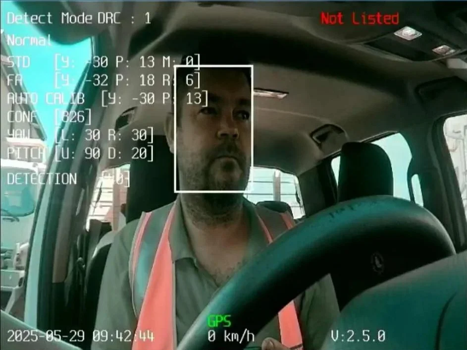

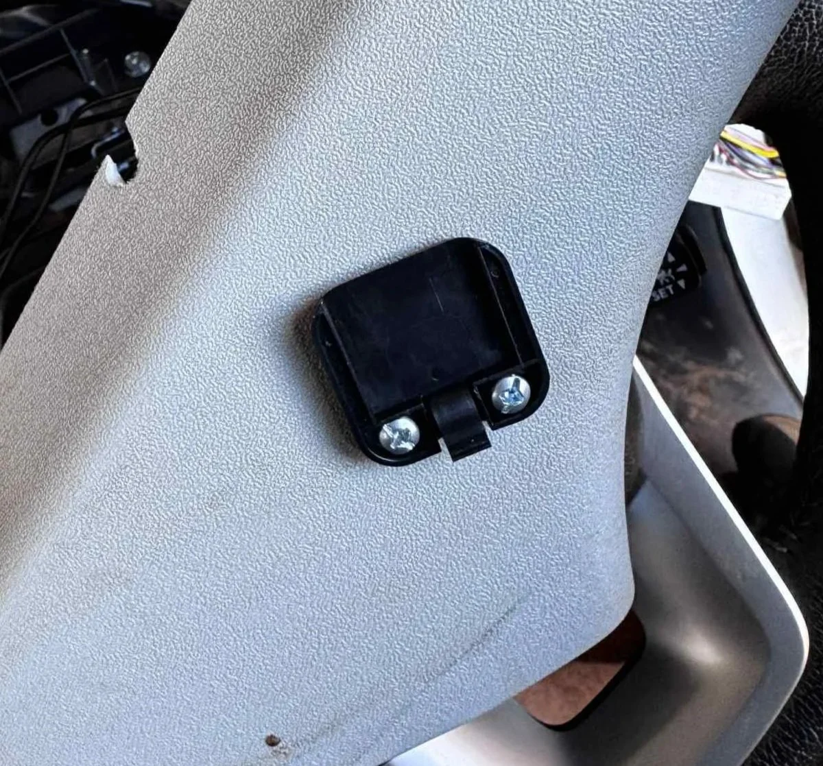
Make sure to use the camera system specific mobile app to live view the driver facing camera for optimal positioning - Instruction on the app below.
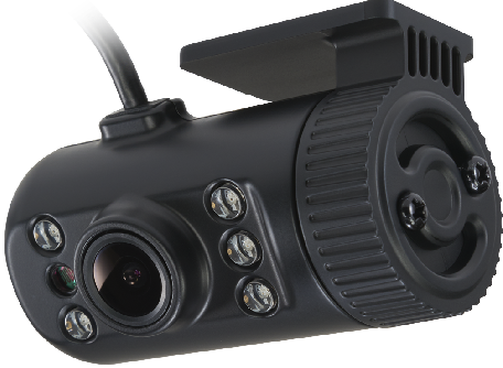
Secondary Camera
The secondary camera can be placed on the windscreen facing forward (out side the vehicle) or be used as a secondary in cabin camera. This camera is used as a “dash cam” style camera to give a clearer understanding of the events triggered by the driver facing camera.
The secondary camera cannot be live viewed by the mobile app and only records video to the camera modem (depending on configuration)
Seat Vibrator Installation & Seatbelt Latch Connection
Safety & scope
Do not probe or splice any SRS/airbag wiring (typically yellow looms/connectors), pretensioners, or occupancy mats.
If unsure about a circuit, consult wiring data or use an add-on switch/buffered input rather than tapping SRS lines.
Disconnect the module power before routing/terminating wires.
Materials & wiring spec
Seatbelt trigger lead: 0.5–0.75 mm² (≈20–18 AWG) automotive cable.
Protection: split-loom conduit, fabric tape for anti-rattle, edge grommets.
Routing
Route the vibration power and seatbelt trigger leads together in loom for a neat install.
Leave 50–100 mm service loops at moving points (seat rails, height/tilt) so full seat travel doesn’t strain the wiring.
Secure every 150–200 mm to non-moving structures; avoid sharp edges, heaters, and moving mechanisms.
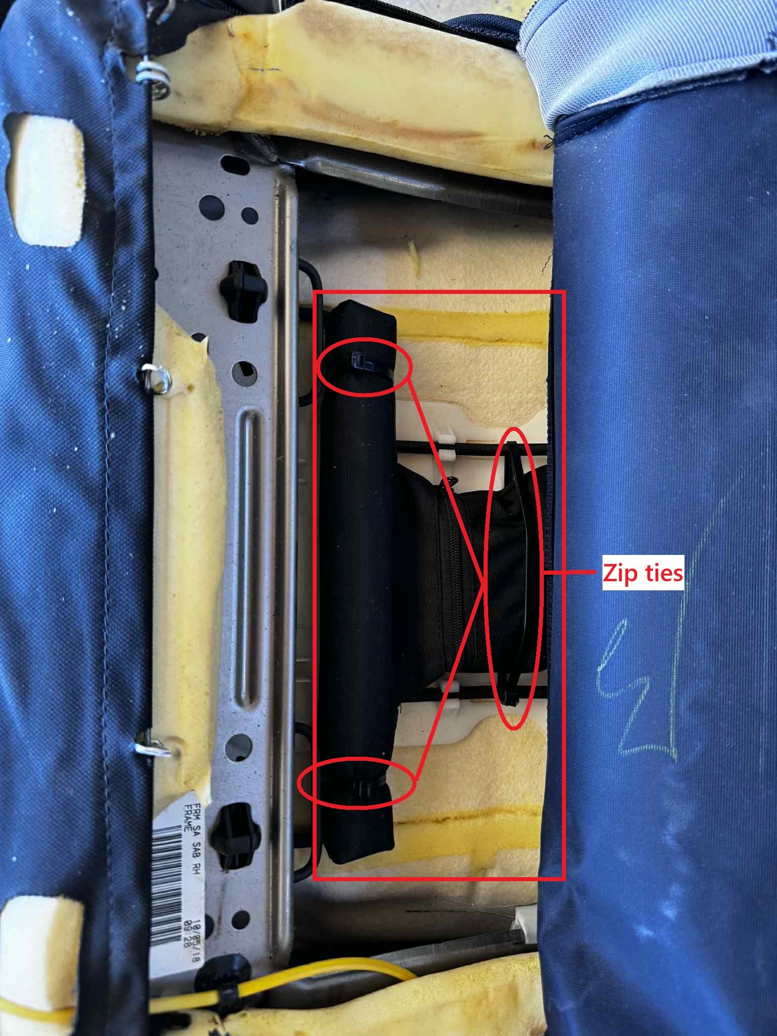
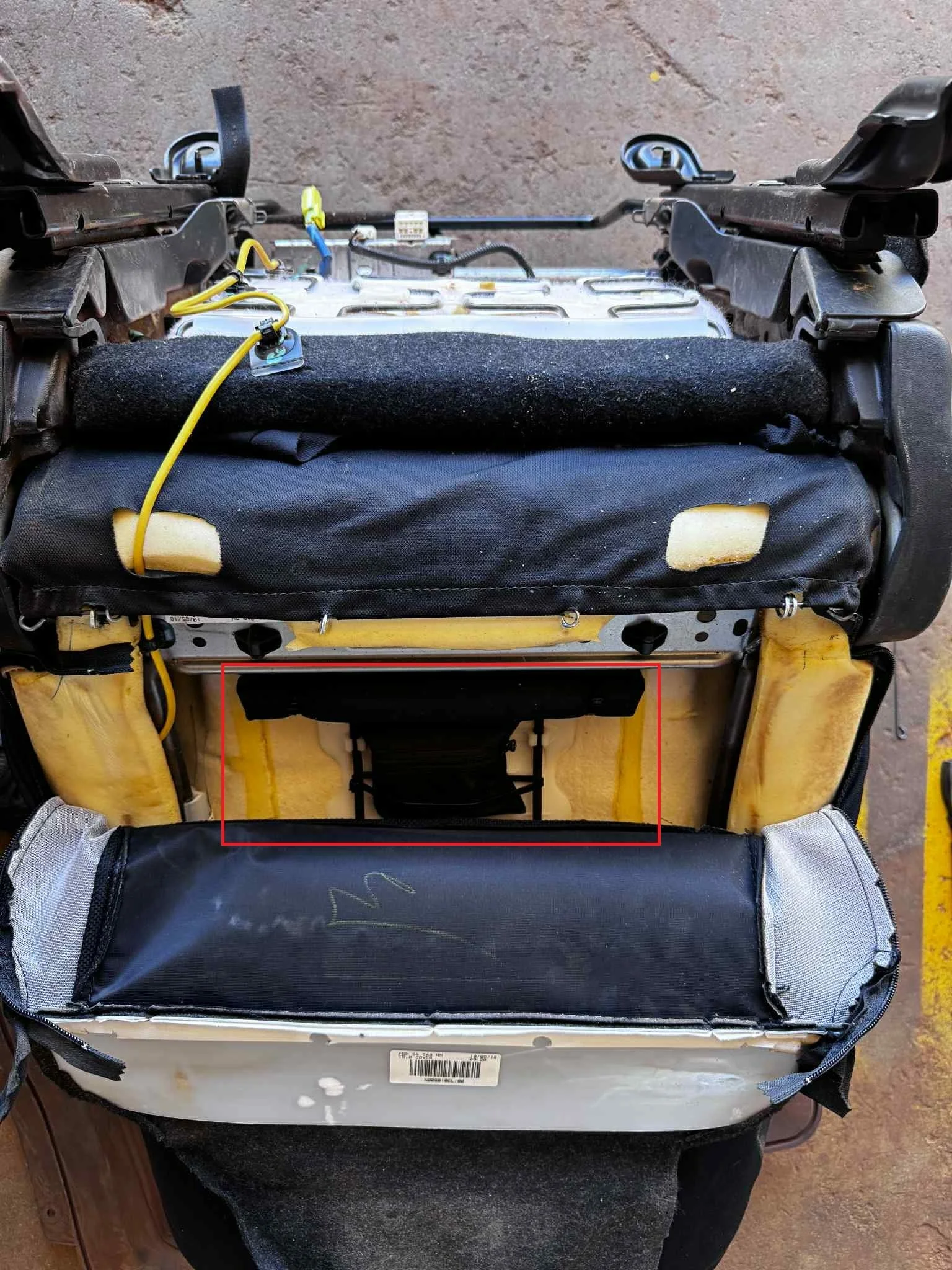
Module mounting
Ensure the module’s power switch is ON (on the vibrator unit).
Mount inside the seat trim where it won’t affect seating position, lumbar, or heaters.
Use zip-ties to secure the vibration module.
After mounting, run the seat through full fore/aft/height travel and confirm no contact, pinch, or change to seating comfort.
Seatbelt latch connection (trigger)
Locate the vehicles seatbelt latch signal wire if available.
Test signal wire by latching and unlatching the seatbelt. Some signal wires are negatively switched.
Connect seatbelt trigger wire from FMC650 DIN2 WHT/GRN.
NOTE:
FMC640 DIN2 is positive latch/input only
FMC650 DIN can be either positive or negative input
Camera System Update and configuration
DISCLAIMER
Scope:
This page will guide you through updating the MDSM-22 camera to the latest firmware via the mobile app and PC.
The main account holder must understand that having access to these login details allows access to the camera settings and video footage. It is possible to delete video footage from camera and change settings that can cause the camera system to not operate as LMS intended.
LMS cannot be held accountable for misuse, deleting of video footage, changing settings outside of the LMS recommended default settings.
PC Update Video
PC Login details:
URL: 30.0.0.1:18087
U/N: admin
P/W: 1234
Mobile App Video
Download the Movon mobile app

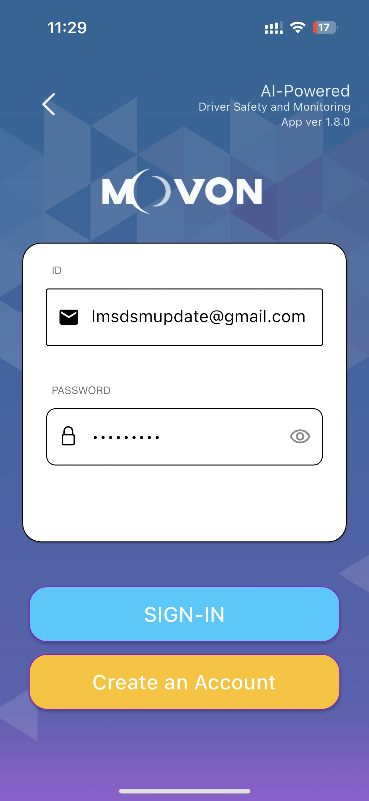
Once downloaded, open the app and select “Installer”.

Input the login details:
U/N: lmsdsmupdate@gmail.com
P/W: Password1
Connecting to the MDSM-22 device is different on Android and IOS
Firstly, press and hold the button on the side of the AI camera for 6 beeps to activate the WIFI on the MDSM-22 module.
Apple IOS device connection
Open up your WIFI menu in mobile settings and select the MDSM22… WIFI device.
Enter the default password: 123456789

Once connected, return to the Movon mobile app and select “Connect to Device”.

Android devices connection
You can search for the MDSM-22 device and connect via the app.
Select “Connect to Device” then click on the MDSM-22 device in the list.


Once the app is connected to the DSM device, you will be presented with the main menu.
To check for updates, select the “Update” option and follow the prompts to update the device.

When the transmitting has complete, allow about 1 minute for the update to be written to the device. Once complete the camera will emit a chime sound.
Now power down the device and wait for all the lights (including the side button light) to turn off.
Power the camera back on and connect following the previous steps.


Select the update menu to make sure the update has completed successfully.

Checking the baud Rate
After updating the firmware, make sure to double check the baud rate.
Return back to the home page and select settings, then other settings


Select the top option - (RS232 Baud Rate)
Make sure 115200 is selected. If 115200 is not selected by default, make sure your select 115200 then return to the previous page and select the save icon up the top right corner.


Now the update process is complete.
Fatigue Management System Commissioning
Key Notes and Considerations
Make sure access to the tracking platform is available to complete system commissioning prior to releasing the vehicle. If access to the Platform is not obtainable, please schedule a remote session with LMS support with 48hour prior notice.
Make sure the commissioning process is completed outside in an unobstructed area; Workshops, tin roofs, tall building, large mining equipment, overhead powerlines etc can all have a negative effect on 4G/GPS signal causing delays to the platform.
It is advised to drive the vehicle “around the block” to allow the GPS signal to get a correct position fix. Without a GPS position fix, the device may show offline on the platform.
Depending on device location and signal, delays of up to 30+ seconds can be experienced between the device and tracking platform when testing features on the tracking system.

Once the system has been installed and camera system has been correctly updated / configured, the system needs to have the minimum functions tested:
Device shows online and live tracks.
Iridium Edge Tested if applicable (schedule activation appointment with LMS support).
Camera system shows READY state via the Camera State sensor when ignition on after approximately 1 minute.
An image from the device has been received by the platform (An ignition on photo is acceptable).
Seatbelt sensor latch shows correct state when unplugged and plugged in.
This can be completed via the GPS platform & or with a scheduled remote session with an LMS support tech.